

Introduction: Arduino Motor Shield Tutorial


The Arduino Motor Shield allows you to easily control motor direction and speed using an Arduino. By allowing you to simply address Arduino pins, it makes it very simple to incorporate a motor into your project. It also allows you to be able to power a motor with a separate power supply of up to 12v. Best of all, the shield is very easy to find. For all of these reasons, the Arduino Motor Shield if a cool little to have in your arsenal for rapid prototyping, and general experimenting.
(Note that some of the links on this page are affiliate links. This does not change the cost of the item for you. I reinvest whatever proceeds I receive into making new projects. If you would like any suggestions for alternative suppliers, please let me know.)
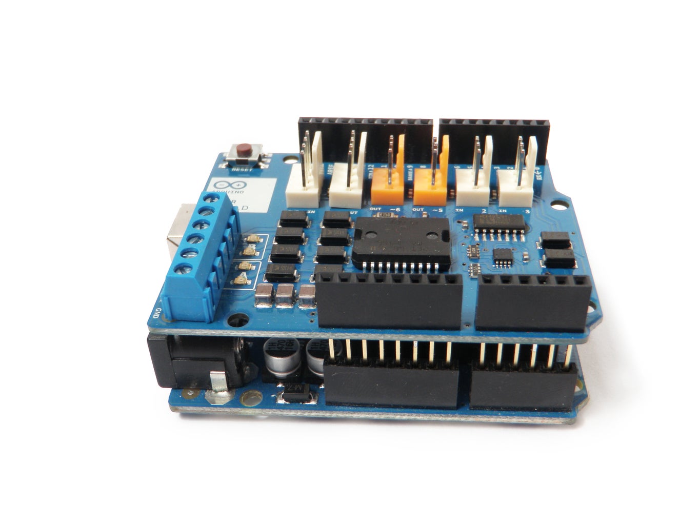
Step 1: Install
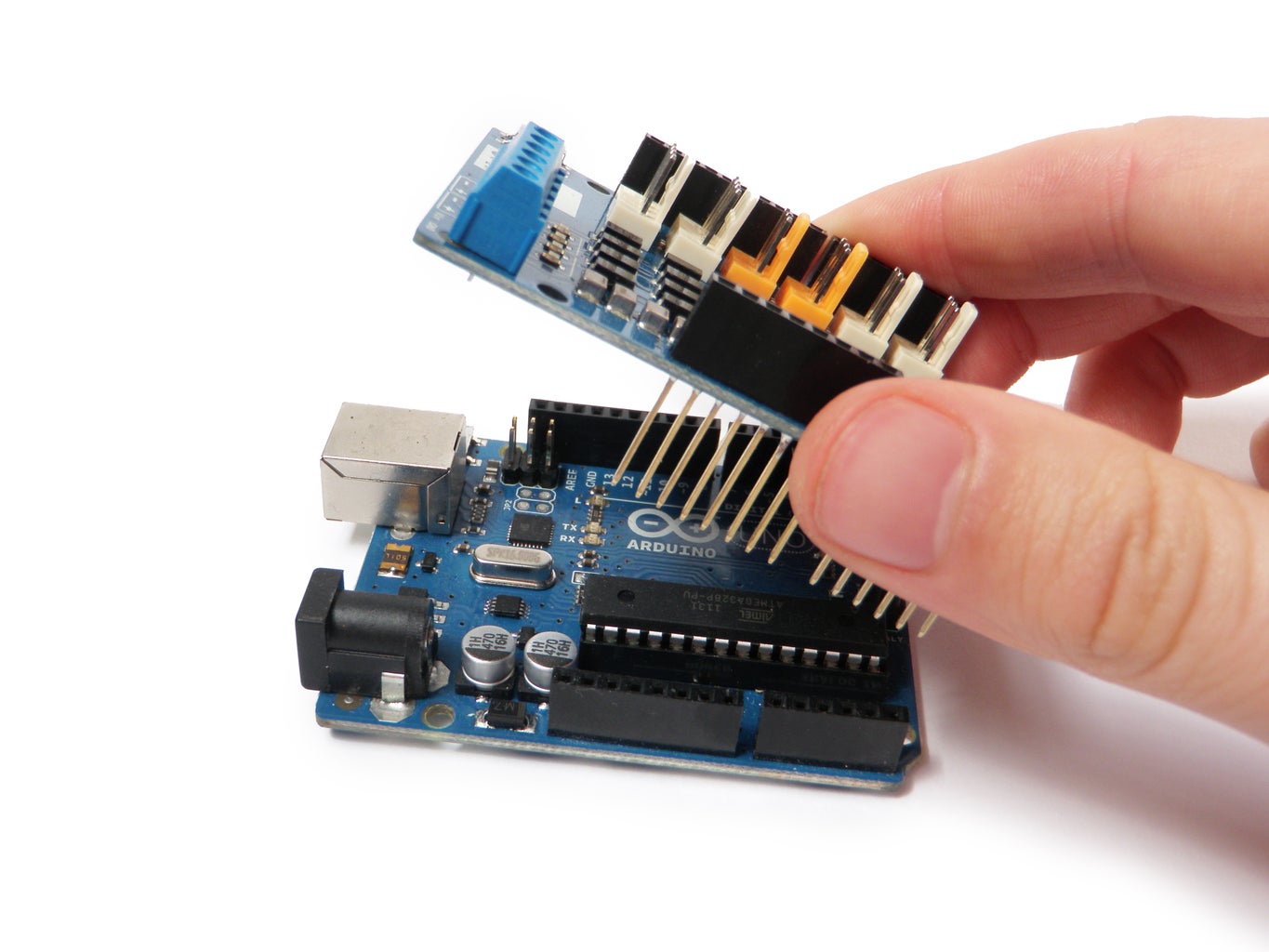
The pins of the official Arduino motor shield will only align with Arduino Uno Rev. 3.
In order to make it work with older versions of the Arduino, you will need to trim a few pins off the motor shield. However, this is not, at all, recommended.
Insert the motor shield pins into the socket of the Arduino Uno.
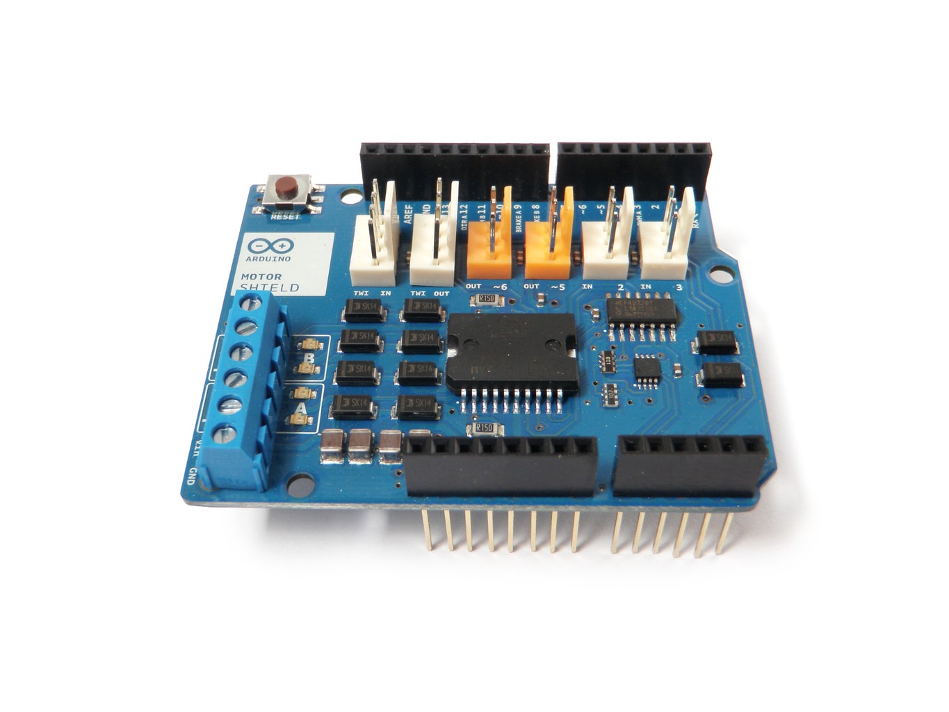
Step 2: Shield Features
The motor shield has 2 channels, which allows for the control of two DC motors, or 1 stepper motor.
It also has 6 headers for the attachment of Tinkerkit inputs, outputs, and communication lines. The use of these pins is somewhat limited, and therefor not covered in this tutorial.
With an external power supply, the motor shield can safely supply up to 12V and 2A per motor channel (or 4A to a single channel).
There are pins on the Arduino that are always in use by the shield. By addressing these pins you can select a motor channel to initiate, specify the motor direction (polarity), set motor speed (PWM), stop and start the motor, and monitor the current absorption of each channel .
The pin breakdown is as follows:
| Function | Channel A | Channel B |
| Direction | Digital 12 | Digital 13 |
| Speed (PWM) | Digital 3 | Digital 11 |
| Brake | Digital 9 | Digital 8 |
| Current Sensing | Analog 0 | Analog 1 |
For more information about the technical specs, check out the motor shield's official page on the Arduino site.
Step 3: Program

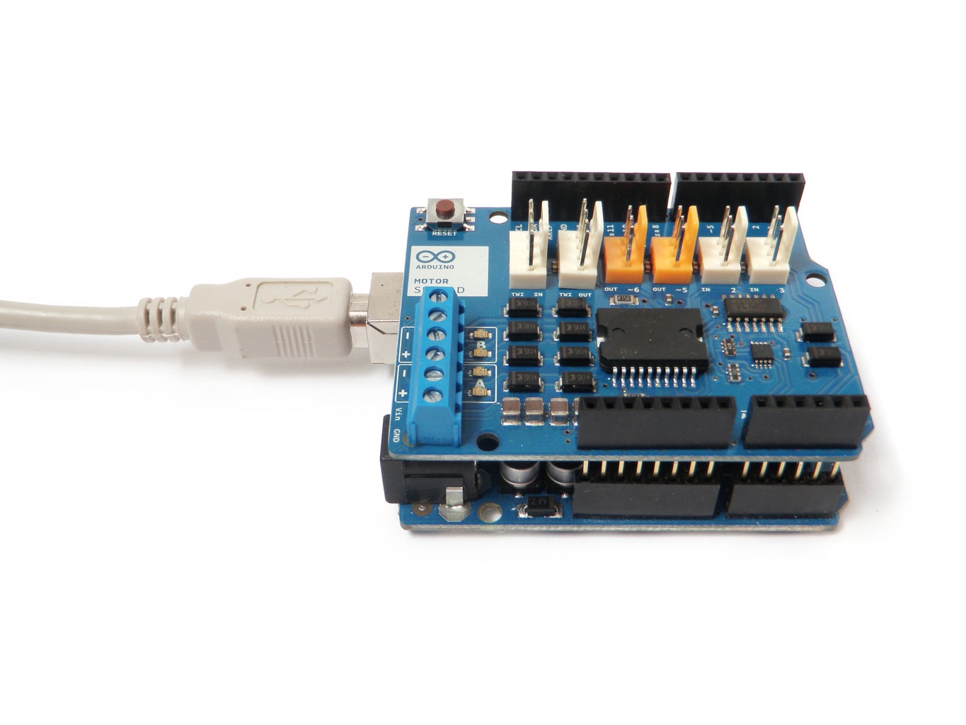
Plug the Arduino into your computer's USB port and open the Arduino development environment.
In order to get the board to do anything, you need to initialize the motor channel by toggling three parameters:
- First you need to set the motor direction (polarity of the power supply) by setting it either HIGH or LOW.
- Then you need to disengage the brake pin for the motor channel by setting it to LOW.
- Finally, to get the motor to start moving, you need to set the speed by sending a PWM command (analogWrite) to the appropriate pin.
If you do not do all three of these things, the motor will not turn on.
In the following steps are some common examples of common motor setups.
Step 4: One Motor
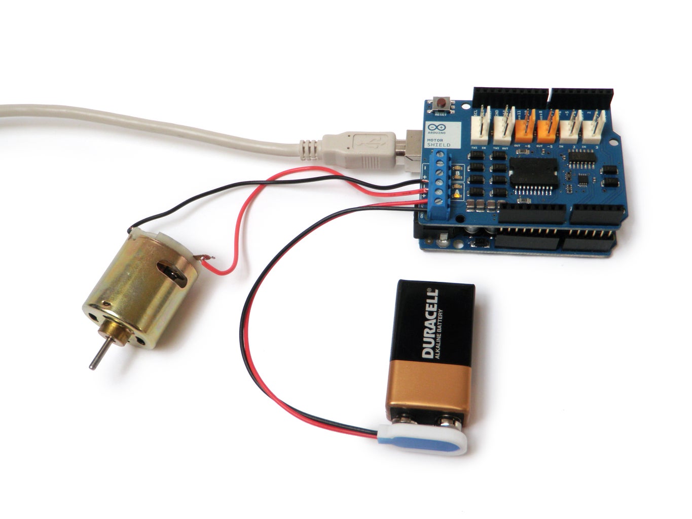

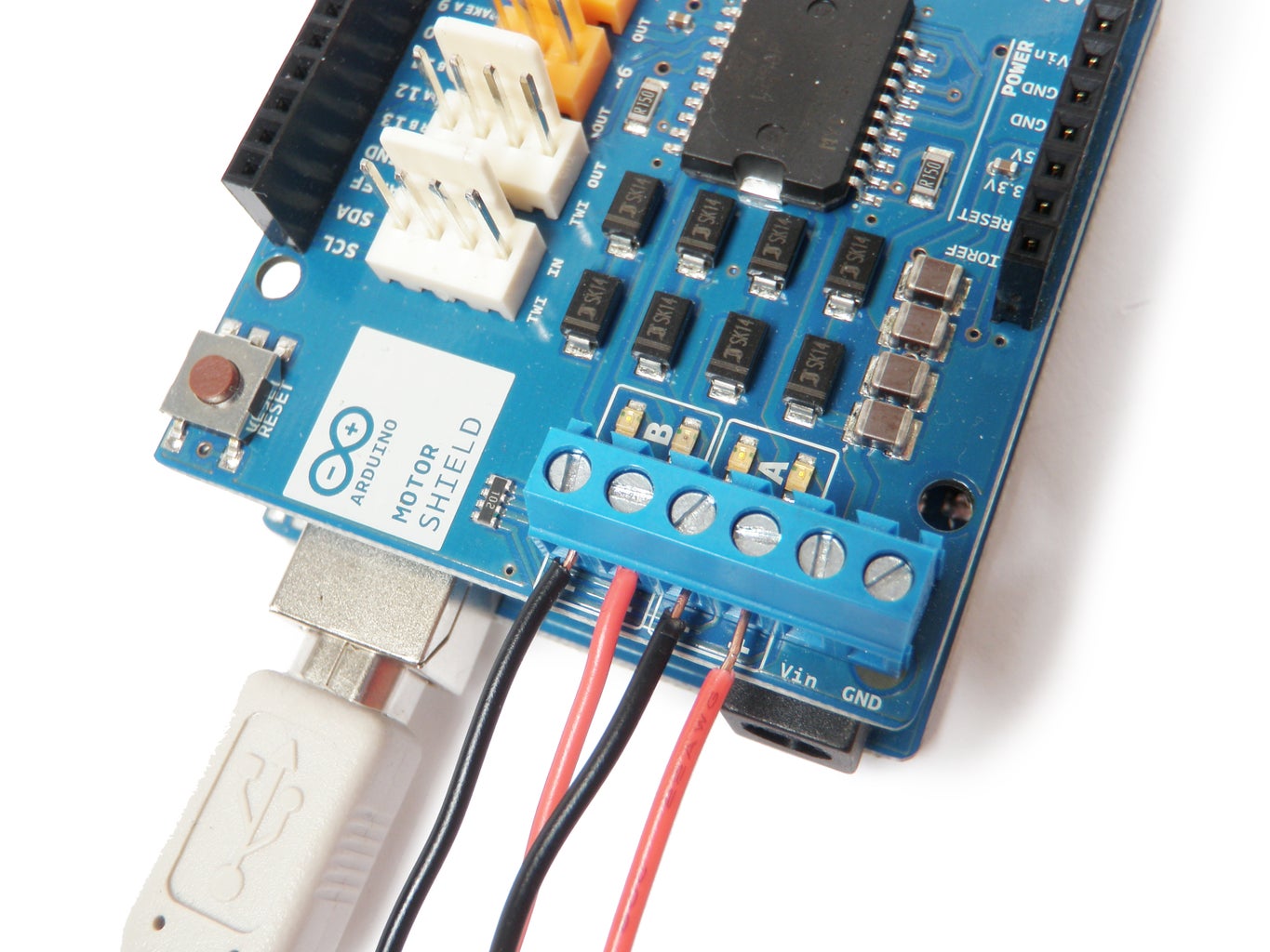
To control a motor using the Arduino Motor Shield, first plug the motor's positive (red) wire into Channel A's + terminal on the motor shield, and the motor's ground (black) wire into Channel A's - terminal on the shield.
An external power supply is not always necessary, but it drastically improves the motor's performance. It is recommended that you always use one.
To connect your external power supply, connect the positive (red) wire from the power supply to the "Vin" terminal, and the ground (black) wire to the "GND" terminal.
Finally, upload the code to control the Motor Shield to the Arduino.
Here is the code for controlling one motor:<pre>/*************************************************************
Motor Shield 1-Channel DC Motor Demo
by Randy Sarafan
For more information see:
https://www.instructables.com/id/Arduino-Motor-Shield-Tutorial/
*************************************************************/
void setup() {
//Setup Channel A
pinMode(12, OUTPUT); //Initiates Motor Channel A pin
pinMode(9, OUTPUT); //Initiates Brake Channel A pin
}
void loop(){
//forward @ full speed
digitalWrite(12, HIGH); //Establishes forward direction of Channel A
digitalWrite(9, LOW); //Disengage the Brake for Channel A
analogWrite(3, 255); //Spins the motor on Channel A at full speed
delay(3000);
digitalWrite(9, HIGH); //Eengage the Brake for Channel A
delay(1000);
//backward @ half speed
digitalWrite(12, LOW); //Establishes backward direction of Channel A
digitalWrite(9, LOW); //Disengage the Brake for Channel A
analogWrite(3, 123); //Spins the motor on Channel A at half speed
delay(3000);
digitalWrite(9, HIGH); //Eengage the Brake for Channel A
delay(1000);
}
Step 5: Two Motors
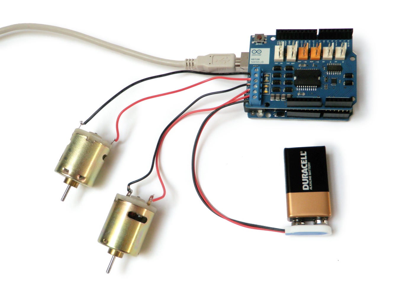
Interfacing with two motors is pretty much the same as interfacing with one motor. Simply plug the motor into Channel B.
The only difference code-wise is that you need to engage a second channel to control the second motor.
Here is code for controlling two motors:<pre>/*************************************************************
Motor Shield 2-Channel DC Motor Demo
by Randy Sarafan
For more information see:
https://www.instructables.com/id/Arduino-Motor-Shield-Tutorial/
*************************************************************/
void setup() {
//Setup Channel A
pinMode(12, OUTPUT); //Initiates Motor Channel A pin
pinMode(9, OUTPUT); //Initiates Brake Channel A pin
//Setup Channel B
pinMode(13, OUTPUT); //Initiates Motor Channel A pin
pinMode(8, OUTPUT); //Initiates Brake Channel A pin
}
void loop(){
//Motor A forward @ full speed
digitalWrite(12, HIGH); //Establishes forward direction of Channel A
digitalWrite(9, LOW); //Disengage the Brake for Channel A
analogWrite(3, 255); //Spins the motor on Channel A at full speed
//Motor B backward @ half speed
digitalWrite(13, LOW); //Establishes backward direction of Channel B
digitalWrite(8, LOW); //Disengage the Brake for Channel B
analogWrite(11, 123); //Spins the motor on Channel B at half speed
delay(3000);
digitalWrite(9, HIGH); //Engage the Brake for Channel A
digitalWrite(9, HIGH); //Engage the Brake for Channel B
delay(1000);
//Motor A forward @ full speed
digitalWrite(12, LOW); //Establishes backward direction of Channel A
digitalWrite(9, LOW); //Disengage the Brake for Channel A
analogWrite(3, 123); //Spins the motor on Channel A at half speed
//Motor B forward @ full speed
digitalWrite(13, HIGH); //Establishes forward direction of Channel B
digitalWrite(8, LOW); //Disengage the Brake for Channel B
analogWrite(11, 255); //Spins the motor on Channel B at full speed
delay(3000);
digitalWrite(9, HIGH); //Engage the Brake for Channel A
digitalWrite(9, HIGH); //Engage the Brake for Channel B
delay(1000);
}
Step 6: Stepper Motor


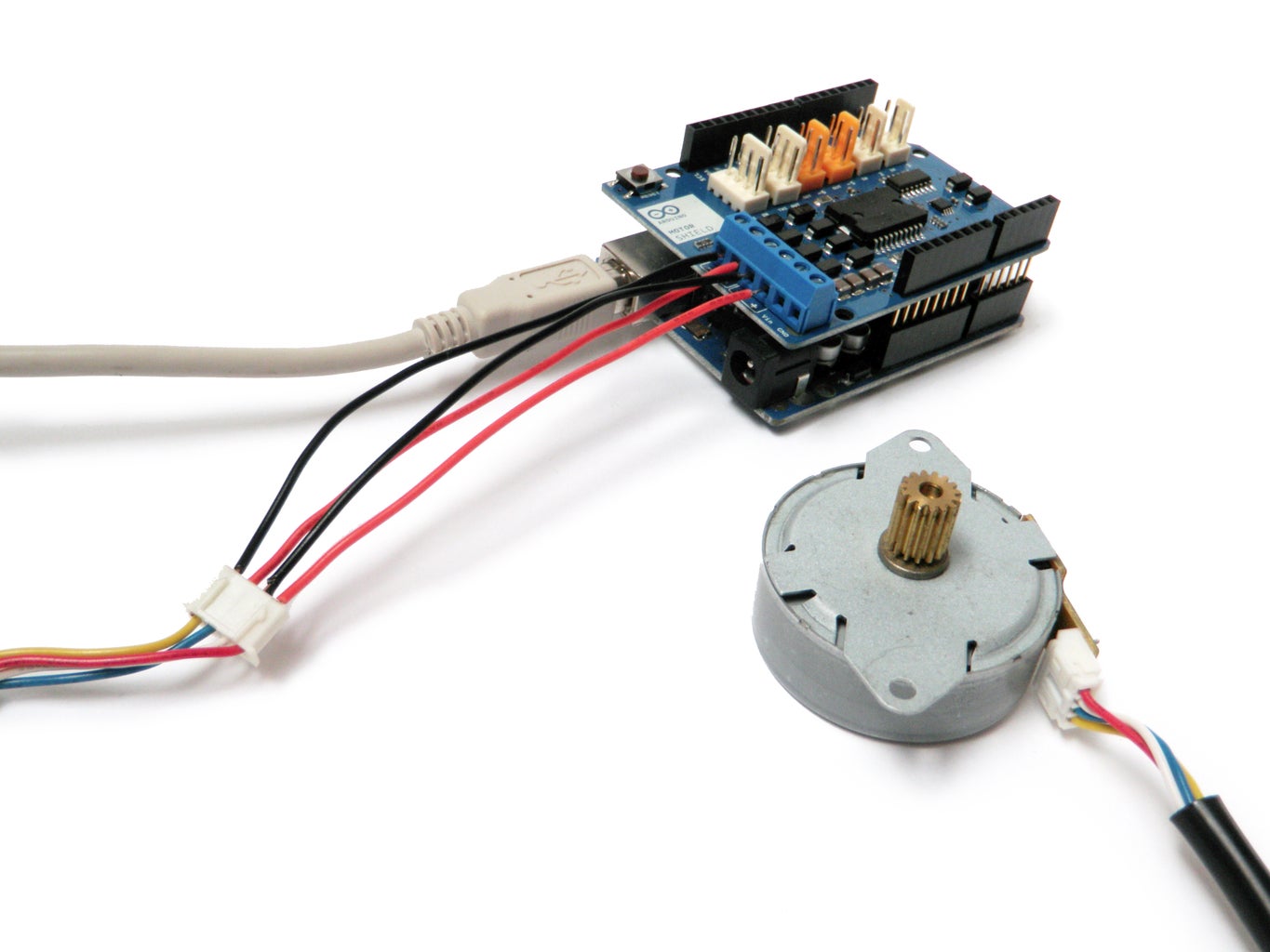
There are a number of different types of stepper motors, but in this tutorial we will specifically be addressing bipolar stepper motors. Bipolar stepper motors typically have 4 pins, which correspond to two coils. To use a stepper, you need to power these two coils in phase with alternating polarity.
To figure out which two pins make up a single coil, insert an LED into any two pins on its socket and rotate the motor shaft. If the LED lights up, you found one coil. The other two pins should make up the other coil.
To make a bipolar motor spin:
- Power the first coil.
- Next power the second coil with reverse polarity.
- Then power the first coil with reverse polarity.
- Finally, power the second coil.
To reverse the motor direction of a bipolar stepper, simply reverse the polarity of the second coil.
Here is code to make the stepper spin in one direction:<pre>/*************************************************************
Motor Shield Stepper Demo
by Randy Sarafan
For more information see:
<a href="https://www.instructables.com/id/Arduino-Motor-Shield-Tutorial/">
https://www.instructables.com/id/Arduino-Motor-Sh...</a>
*************************************************************/
int delaylegnth = 30;
void setup() {
//establish motor direction toggle pins
pinMode(12, OUTPUT); //CH A -- HIGH = forwards and LOW = backwards???
pinMode(13, OUTPUT); //CH B -- HIGH = forwards and LOW = backwards???
//establish motor brake pins
pinMode(9, OUTPUT); //brake (disable) CH A
pinMode(8, OUTPUT); //brake (disable) CH B
}
void loop(){
digitalWrite(9, LOW); //ENABLE CH A
digitalWrite(8, HIGH); //DISABLE CH B
digitalWrite(12, HIGH); //Sets direction of CH A
analogWrite(3, 255); //Moves CH A
delay(delaylegnth);
digitalWrite(9, HIGH); //DISABLE CH A
digitalWrite(8, LOW); //ENABLE CH B
digitalWrite(13, LOW); //Sets direction of CH B
analogWrite(11, 255); //Moves CH B
delay(delaylegnth);
digitalWrite(9, LOW); //ENABLE CH A
digitalWrite(8, HIGH); //DISABLE CH B
digitalWrite(12, LOW); //Sets direction of CH A
analogWrite(3, 255); //Moves CH A
delay(delaylegnth);
digitalWrite(9, HIGH); //DISABLE CH A
digitalWrite(8, LOW); //ENABLE CH B
digitalWrite(13, HIGH); //Sets direction of CH B
analogWrite(11, 255); //Moves CH B
delay(delaylegnth);
}
Here is code to make the stepper spin in the opposite direction:
<pre>/*************************************************************
Motor Shield Stepper Demo
by Randy Sarafan

For more information see:
<a href="https://www.instructables.com/id/Arduino-Motor-Shield-Tutorial/">
https://www.instructables.com/id/Arduino-Motor-Sh...</a>

*************************************************************/

int delaylegnth = 30;

void setup() {

  //establish motor direction toggle pins
  pinMode(12, OUTPUT); //CH A -- HIGH = forwards and LOW = backwards???
  pinMode(13, OUTPUT); //CH B -- HIGH = forwards and LOW = backwards???

  //establish motor brake pins
  pinMode(9, OUTPUT); //brake (disable) CH A
  pinMode(8, OUTPUT); //brake (disable) CH B


}

void loop(){

  digitalWrite(9, LOW);  //ENABLE CH A
  digitalWrite(8, HIGH); //DISABLE CH B

  digitalWrite(12, HIGH);   //Sets direction of CH A
  analogWrite(3, 255);   //Moves CH A

  delay(delaylegnth);

  digitalWrite(9, HIGH);  //DISABLE CH A
  digitalWrite(8, LOW); //ENABLE CH B

  digitalWrite(13, HIGH);   //Sets direction of CH B
  analogWrite(11, 255);   //Moves CH B

  delay(delaylegnth);

  digitalWrite(9, LOW);  //ENABLE CH A
  digitalWrite(8, HIGH); //DISABLE CH B

  digitalWrite(12, LOW);   //Sets direction of CH A
  analogWrite(3, 255);   //Moves CH A

  delay(delaylegnth);

  digitalWrite(9, HIGH);  //DISABLE CH A
  digitalWrite(8, LOW); //ENABLE CH B

  digitalWrite(13, LOW);   //Sets direction of CH B
  analogWrite(11, 255);   //Moves CH B

  delay(delaylegnth);

}

Did you find this useful, fun, or entertaining?
Follow @madeineuphoria to see my latest projects.

Participated in the
Arduino Challenge


